Simply Cool and Smart

Peace of Mind
With our CO₂ scroll technology, we enable worry-free solutions tailored to your needs and ensure your peace of mind.
Refrigeration with CO₂ depends on a refrigeration system that operates in a reliable, efficient, and self-contained manner. Therefore, we developed a new generation of scroll compressors equipped with innovative injection technology. You can count on it.
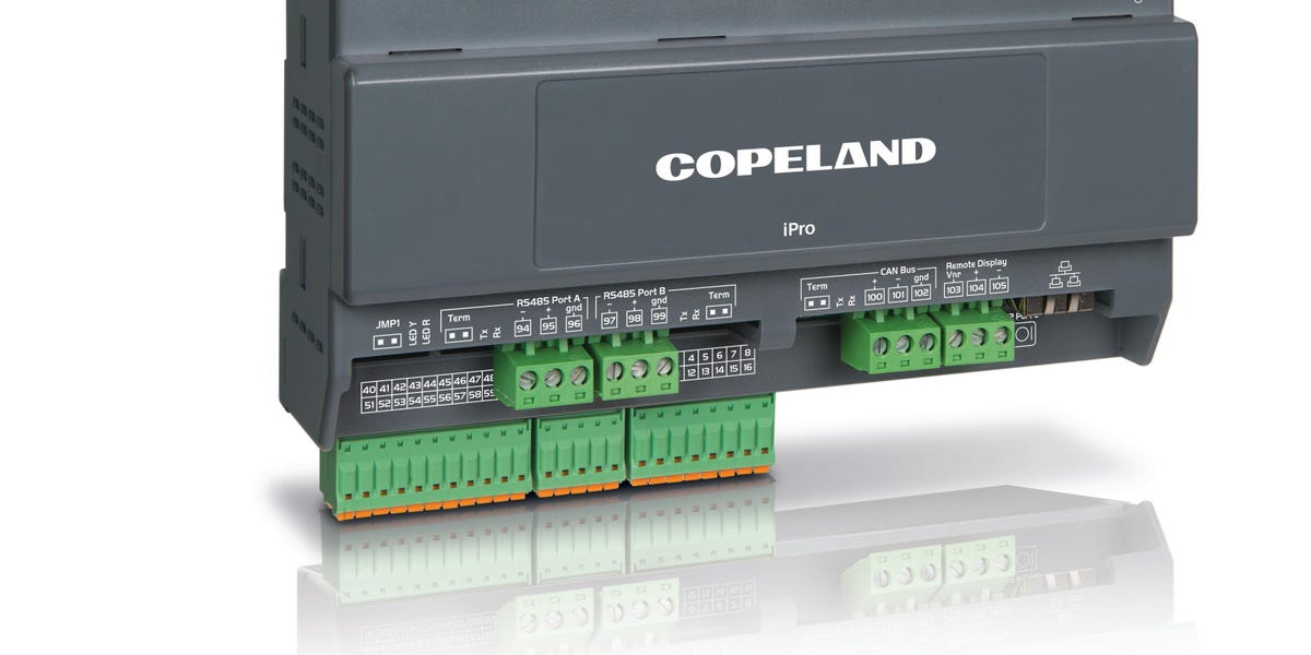
For a refrigeration system to operate perfectly, it is crucial that the refrigerant is injected, compressed, and circulated accurately at exactly the right time. Our new generation of scroll compressors equipped with innovative injection technology for flash gas management are designed to do exactly that. A suite of intelligent electronics optimizes system performance. At the heart of the technology is the new Copeland XC Pro CO₂ scroll controller – designed specifically for booster applications and refrigeration units.
Fewer Components Reduce Complexity
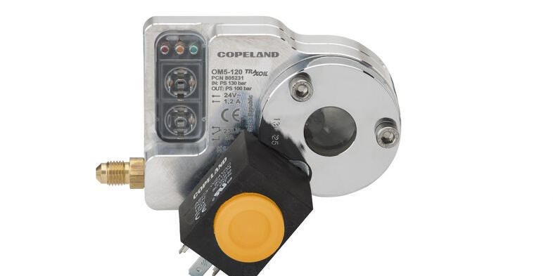
The application of Dynamic Vapor Injection (DVI) allows for flash gas to be directly injected from the economizer or the flash gas tank into the compressor by a dedicated valve. While the controller adjusts the injection pressure to optimize the system performance. This eliminates the need for parallel compression and therefore enables the cooling circuit to be operated with less system components such as parallel compressor with inverter drive. Thanks to DVI, the refrigeration system operates at high efficiency regardless of the climate. And with less components reducing its complexity dramatically.
Higher System Efficiency
The suite of intelligent electronics is managed by the new dedicated Copeland XC Pro CO₂ scroll controller with smart control logic. It monitors, analyzes, and optimizes the different system components to deliver high system efficiency, safe compressor operation and enables lower pressure design.
| SMART AND SAFE
Digitalization of the cooling circuit helps service technicians to make the right diagnostic in case of system problems. |
Many Improvements Digitalization is key when it comes to increasing system performance. It is a means to record, analyze, and evaluate data of the system components and their operation. Connecting our intelligent system controller to a building management system (BMS) provides digitalization benefits such as remote diagnostics, predictive maintenance, performance analysis, and comprehensive data analysis: a holistic smart store management and the ability to draw conclusions from the data for further process optimization. |
The Cooling Circuit
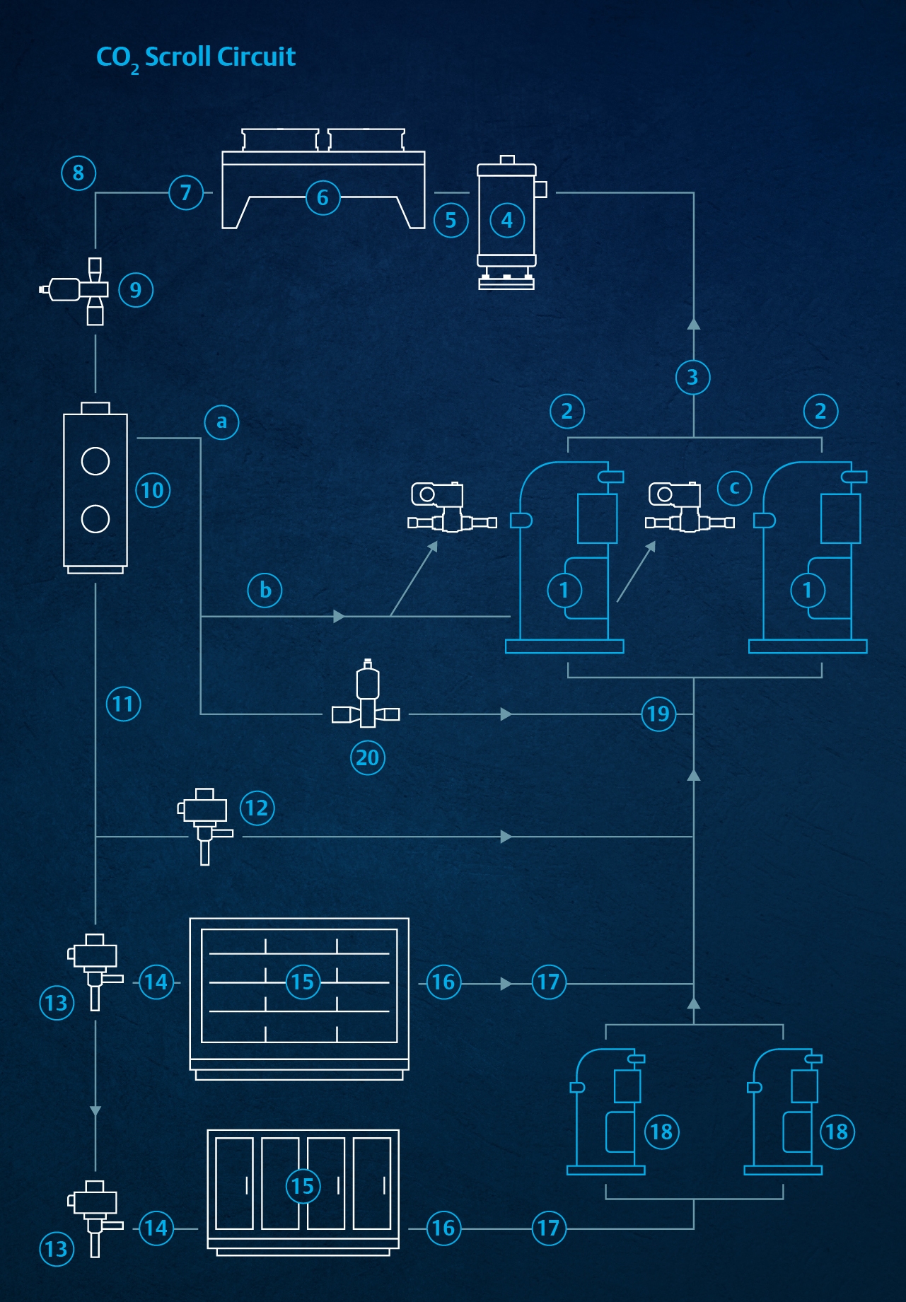
The intelligent control from the Copeland XC Pro CO2 scroll controller adjusts all components. The graphic below describes the path of CO2 in the cooling circuit, which is paved with control components at various stations.

The path of CO₂ through the cooling circuit
Main stream circuit
| Nr. | Component/action | surveillance/monitoring | modulation/operation |
|---|---|---|---|
| 1 | Compression in compressor | flow rate, pressure, temperature | drive speed |
| 2 | Discharge valve of compressor | operational status | closing and opening |
| 3 | Discharge line |
flow rate, pressure, temperature | |
| 4 | Oil separator | ||
| 5 | Gas cooler inlet | ||
| 6 | Gas cooler | flow rate, pressure, CO2 temperature, environment temperature, condensation, dirt detection | as a part of predictive maintenance, fan speed |
| 7 | Gas cooler outlet | ||
| 8 | Pipe between gas cooler and high-pressure valve | flow rate, pressure, temperature | |
| 9 | High pressure valve (HPV) | operational status | opening in percent |
| 10 | Flash tank | flow rate, pressure, temperature, flash gas content | |
| 11 | Liquid line | flow rate, pressure, temperature | |
| 12 | Liquid injection valve | ||
| 13 | Expansion valve | operational status | opening in percent |
| 14 | Injection line | flow rate, pressure, temperature | |
| 15 | Evaporator | flow rate, pressure, actual and setpoint temperature | |
| 16 | Evaporator outlet | pressure and temperature of refrigerant | |
| 17 | Suction line | flow rate, pressure, temperature | |
| 18 | Low temperature compressors | ||
| 19 | Connection of bypass to suction line | ||
| 20 | Bypass valve | pressure (flash tank) | opening in percent |
Flash gas stream via DVI circuit
| Nr. | Component/action | surveillance/monitoring | modulation/operation |
|---|---|---|---|
| a | Bypass to remove flash gas from flash tank | ||
| b | Vapor injection line | flow rate, pressure, temperature | |
| c | Injection of flash gas into the compressor |


